
News
BLOGS
Mar 06 / 2026
Coil Winding & Motor Winding Machines: Complete Guide to Electric Motor Coils
- Written by Link Lin, Design
- Technical review by Sam Chen, Technical Director
- Link Lin has over 10 years of experience in coil winding equipment, tooling design, tension control, and motor winding automation.
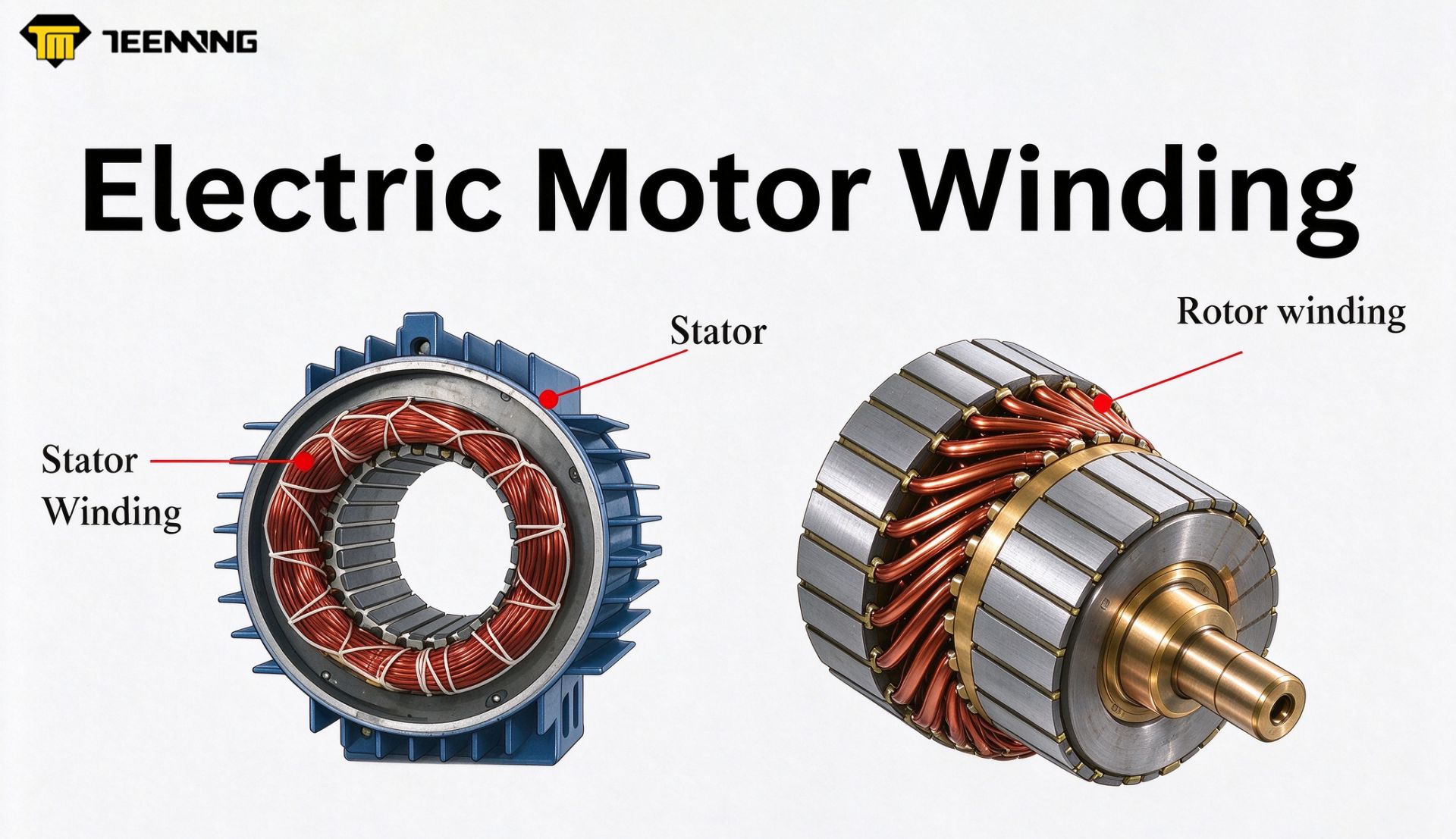
Coil winding is the process of placing insulated copper or aluminum wire around a core, bobbin, stator tooth, or rotor to form an electromagnetic coil. In an electric motor, current flowing through these coils creates a magnetic field that interacts with the stator–rotor magnetic system to produce torque.
A motor winding machine controls wire feeding, tension, placement, turn count, winding direction, and other production steps. Selecting the appropriate winding method and machine configuration helps manufacturers maintain repeatable coil geometry while meeting the electrical and mechanical requirements of each motor design.
Quick Definitions
| Term | Definition |
| Coil winding | The manufacturing process used to place conductive wire around a core, bobbin, stator, rotor, or other component. |
| Electric motor coil | A wound conductor that generates a magnetic field when current flows through it. |
| Motor winding machine | Equipment that controls or automates the winding of wire onto motor stators, rotors, armatures, and related components. |
Article Contents
- What is coil winding?
- What Are Electric Motor Coils and How Do They Work?
- Which parameters affect motor coil performance?
- What is a motor winding machine?
- How does a motor winding machine work?
- What are the main coil winding methods?
- What is the difference between winding methods and winding patterns?
- Stator vs. rotor winding
- How is motor winding quality checked?
- How Do You Choose the Right Motor Winding Machine?
- Teeming motor winding machine solutions
- Motor Winding Automation and Production-Line Integration
- Motor winding machine FAQs
What Is Coil Winding?
Coil winding is the controlled placement of insulated conductive wire around a core, bobbin, former, stator tooth, rotor, or armature. The finished coil produces a magnetic field when electric current passes through the conductor.
Coil winding is used in electric motors, generators, transformers, relays, solenoids, inductors, sensors, and many other electromechanical components. The required winding structure depends on the product geometry, wire size, turn count, electrical design, insulation requirements, and production volume.
A coil winding process generally controls:
- Wire feeding
- Wire tension
- Turn count
- Winding direction
- Wire placement
- Winding speed
- Start and end positions
- Lead-wire handling
- Cutting or termination
- Loading and unloading
Consistent control is important because changes in tension, turn count, wire placement, or insulation condition can alter the dimensions and electrical properties of the finished coil.
What Are Electric Motor Coils and How Do They Work?
Electric motor coils are insulated conductors arranged to create controlled magnetic fields. When current flows through a coil, the resulting magnetic field interacts with another magnetic field in the motor. This interaction produces the force required to generate torque and rotation.
Depending on the motor design, coils may be located on the stator, rotor, or armature.
- The stator is the stationary part of the motor. Its windings commonly generate a stationary or rotating magnetic field.
- The rotor is the rotating part. Some rotors contain wound conductors, while permanent-magnet and squirrel-cage rotor designs use different structures.
- The armature is the part in which electromotive force is induced. Its physical position depends on the motor architecture.
Electric motor coils are commonly made from enamel-insulated copper wire. Aluminum wire may also be used in applications where weight, material cost, or other design requirements make it suitable. The insulation coating normally remains on the conductor during winding and is removed only where an electrical termination must be made.
Which Parameters Affect Electric Motor Coil Performance?
Motor coil performance is not determined by one parameter alone. The electrical design, winding process, material, motor geometry, and production controls work together.
| Parameter | Effect on the motor coil |
| Number of turns | Influences magnetic field strength, voltage characteristics, inductance, and resistance. |
| Wire diameter | Affects current capacity, electrical resistance, available winding space, and mechanical handling. |
| Wire material | Influences resistance, weight, thermal behavior, and termination requirements. |
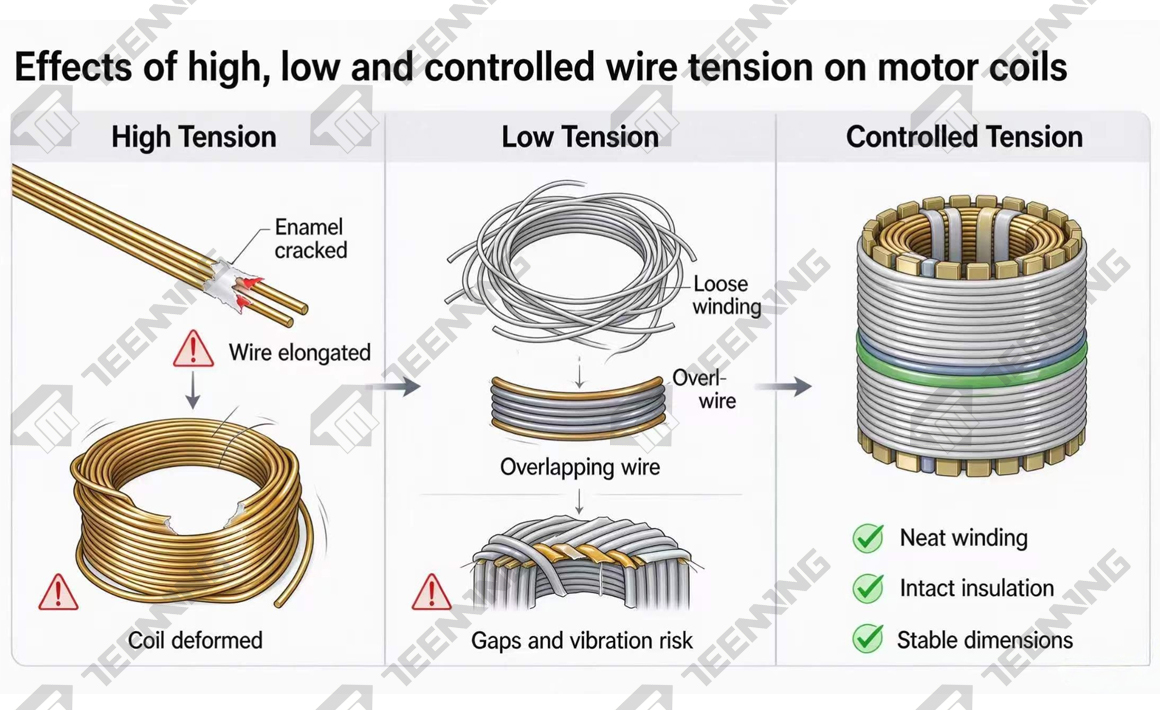
| Wire tension | Affects coil geometry, packing consistency, and the risk of stretching or damaging the insulation. |
| Winding direction | Determines magnetic polarity and must match the phase and connection design. |
| Slot fill factor | Describes how much available winding space is occupied by the conductor and insulation system. |
| Insulation system | Affects dielectric strength, temperature resistance, and long-term reliability. |
| Winding speed | Influences production output but must remain compatible with the wire, tooling, tension, and product geometry. |
| Lead-wire position | Affects termination, welding, soldering, assembly, and downstream automation. |
For a detailed discussion of turn count, wire diameter, resistance, inductance, and slot fill factor, see Motor Coil Winding and Motor Winding Calculation.
For polarity and CW/CCW winding, see Motor Coil Winding and Coil Winding Direction.
What Is a Motor Winding Machine?
A motor winding machine is a mechanical or automated system used to place conductive wire onto a motor stator, rotor, armature, or other magnetic core according to programmed parameters.
Depending on the machine and production requirements, the system may control:
- Needle, flyer, spindle, or other winding motion
- Wire tension
- Winding speed
- Turn count
- CW or CCW winding direction
- Wire-guide position
- Slot or pole indexing
- Lead-wire routing
- Pin wrapping
- Wire cutting
- Tooling position
- Product loading and unloading
- Production data and alarm monitoring
Manual equipment relies more heavily on operator control. Automatic motor winding machines use servo motors, controllers, sensors, programmable recipes, and purpose-built tooling to improve repeatability and support larger production volumes.
How Does a Motor Winding Machine Work?
Although the exact process depends on the motor and winding method, an automatic motor winding cycle generally follows these steps.
1. Load the Workpiece
The stator, rotor, armature, or core is secured in a fixture. Loading may be completed manually or by a robot, depending on the required automation level.
2. Load and Guide the Wire
The wire passes from the spool through a tensioner and wire-guiding system. The tension setting must match the conductor diameter, insulation, winding speed, and product geometry.
3. Set the Winding Parameters
The operator selects or enters the production recipe, including:
- Turn count
- Winding speed
- Winding direction
- Wire-guide path
- Slot or pole sequence
- Tension settings
- Start and end positions
4. Wind the Coil
The machine moves the needle, flyer, wire guide, spindle, or workpiece according to the programmed path. Servo control may coordinate several axes to place the wire within the required slots or around the specified core geometry.
5. Handle the Lead Wire
Depending on the application, the machine may route the lead wire, wrap it around a terminal pin, cross between slots, or prepare it for welding or soldering.
6. Cut or Secure the Wire
After the required turns are completed, the wire may be cut, clamped, wrapped, welded, or transferred to a downstream station.
7. Unload and Inspect
The finished component is unloaded manually or automatically. Inspection may include resistance, continuity, inductance, insulation, dimensional, visual, or functional checks according to the production specification.
What Are the Main Coil Winding Methods?
A winding method describes how the wire and workpiece move during production. The appropriate method depends on the component geometry, winding location, wire size, slot accessibility, and required output.
| Winding method | How it works | Typical applications | Main considerations |
| Spindle or linear winding | The workpiece rotates while the wire guide moves along the winding axis. | Bobbin coils, cylindrical coils, relays, solenoids, and some rotor designs. | Requires suitable rotating geometry and controlled traverse movement. |
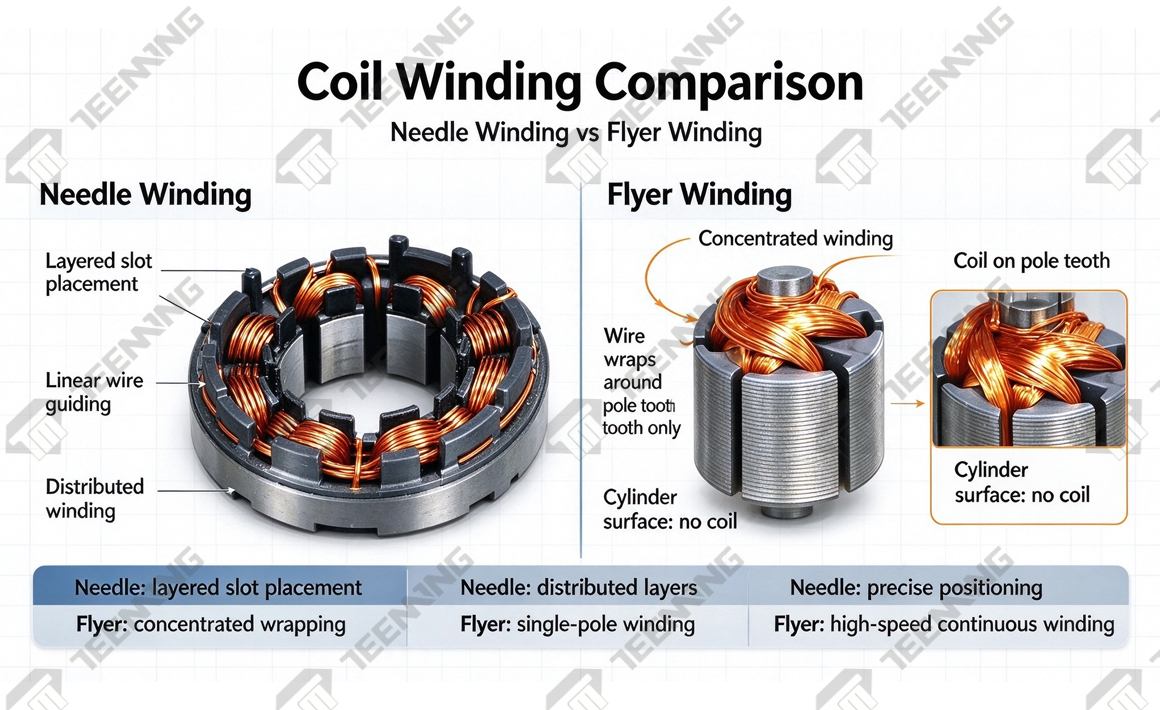
| Needle winding | A needle guides wire through or around stator slots while coordinated axes index the workpiece. | Inner and outer stators, BLDC motors, and compact slotted cores. | Needle clearance, slot opening, wire diameter, and nozzle angle must be evaluated. |
| Flyer winding | A rotating flyer guides wire around a stationary or indexed workpiece. | Rotor, armature, outer-core, and high-speed motor winding applications. | Tooling, commutator or hook configuration, wire tension, and flyer path affect the result. |
| Toroidal winding | The wire or shuttle repeatedly passes through the center of a ring-shaped core. | Toroidal transformers, inductors, and ring cores. | This method requires specialized toroidal winding equipment and is not a typical stator winding process. |
| Hairpin forming and insertion | Preformed rectangular conductors are inserted and joined rather than continuously wound in the traditional manner. | High-volume traction motors and selected automotive applications. | Requires conductor forming, insertion, connection, and welding processes. |
What Is the Difference Between Winding Methods and Winding Patterns?
A winding method describes the movement of the machine, wire, and workpiece. A winding pattern describes how adjacent turns are arranged within the finished coil.
These terms are related but are not interchangeable.
| Winding pattern | Structure | Advantages | Main considerations |
| Random or wild winding | Turns are placed without a strictly ordered layer pattern. | Faster production and greater tolerance for some product geometries. | Coil dimensions and packing may be less uniform. |
| Layer winding | Turns are arranged in defined layers. | Predictable dimensions and more consistent placement. | Requires accurate traverse movement and tension control. |
| Orthocyclic winding | Each turn is positioned in a defined geometric relationship with adjacent turns. | High packing density and repeatable coil geometry. | Requires precise wire placement and a suitable wire-to-coil geometry. |
| Helical winding | Wire follows a spiral path along a cylindrical or elongated core. | Suitable for solenoids, sensors, and cylindrical coils. | Pitch, traverse speed, and core geometry must be coordinated. |
A single winding machine may produce more than one pattern if its motion control, tooling, wire guide, and tension system support the required arrangement.
Stator vs. Rotor Winding: What Is the Difference?
The stator and rotor perform different functions, so their winding equipment and tooling requirements also differ.
| Aspect | Stator winding | Rotor or armature winding |
| Position | Stationary part of the motor | Rotating part of the motor |
| Winding requirement | Common in AC, BLDC, stepper, servo, and other motor types | Used only in motor designs that require a wound rotor or armature |
| Common methods | Needle winding, flyer winding, insertion-based processes | Flyer winding, hook winding, spindle winding, and armature winding |
| Key geometry | Inner or outer stator, slot opening, tooth shape, stack height | Rotor diameter, length, slot count, shaft, commutator, hook, or bar |
| Important controls | Slot indexing, nozzle angle, lead routing, wire crossing, and slot fill | Hook or commutator positioning, flyer path, indexing, and wire placement |
| Typical inspection | Resistance, phase balance, continuity, insulation, dimensions, and visual condition | Resistance, continuity, commutator connection, insulation, balance, and visual condition |
Not every rotor contains a wire winding. Permanent-magnet and squirrel-cage rotors use different electromagnetic structures. The motor design must therefore be reviewed before choosing the winding process.
For more information about stator configurations, see A Complete Guide to Stator Winding Types, Process, and Applications.
How Is Motor Winding Quality Checked?
Quality requirements depend on the motor specification and production process. Common checks include:
Electrical Resistance
Resistance testing helps confirm that the conductor length, wire size, connections, and turn count are consistent with the approved specification. A resistance result alone does not verify every aspect of coil quality.
Continuity
Continuity testing confirms that the electrical path is complete and helps identify broken conductors or incomplete connections.
Inductance
Inductance testing may be used to evaluate winding consistency and electromagnetic characteristics where required by the motor design.
Insulation Integrity
Insulation resistance, dielectric, surge, or other electrical tests may be used according to the product’s voltage and quality requirements.
Dimensional and Visual Inspection
Manufacturers may inspect:
- Coil height and width
- Lead-wire position
- Wire placement
- Slot or end-winding geometry
- Scratched or damaged insulation
- Loose turns
- Crossed or displaced wire
- Terminal and connection quality
Functional Testing
After assembly, the motor may undergo rotation, current, torque, vibration, noise, temperature, or other functional tests.
The appropriate inspection plan must be defined by the motor designer, manufacturer, and applicable production requirements.
How Do You Choose the Right Motor Winding Machine?
The machine should be selected according to the product and process, rather than winding speed alone.
Before evaluating a motor winding machine, prepare the following information:
| Required information | Why it matters |
| Stator, rotor, or armature drawing | Defines the core geometry and tooling requirements. |
| Inner or outer winding | Helps determine whether needle, flyer, or another process is suitable. |
| Product dimensions | Confirms whether the machine travel, fixture, and work envelope are sufficient. |
| Slot and pole count | Determines indexing, winding path, and program requirements. |
| Wire material and diameter | Influences the tensioner, nozzle, guide, cutter, and achievable speed. |
| Required number of turns | Defines the winding recipe and cycle requirements. |
| Winding direction | Confirms CW/CCW and phase or polarity requirements. |
| Target cycle time | Helps determine spindle count, station configuration, and automation level. |
| Production volume | Influences whether manual, semi-automatic, or fully automatic equipment is appropriate. |
| Product changeover frequency | Determines tooling, recipe storage, and adjustment requirements. |
| Lead and terminal requirements | Defines pin wrapping, cutting, soldering, welding, or other downstream processes. |
| Inspection requirements | Determines whether resistance, vision, tension, or other testing should be integrated. |
| MES or production-line integration | Defines communication, traceability, and upstream or downstream automation needs. |
Providing a workpiece sample, 2D or 3D drawing, winding specification, desired cycle time, and quality requirements allows the machine manufacturer to evaluate tooling and process feasibility more accurately.
Teeming Motor Winding Machine Solutions
With 36 years of experience in winding equipment manufacturing, Teeming Machinery develops motor winding machines, tooling, and automated production solutions for stators, rotors, BLDC motors, and other electromagnetic components.
The following models illustrate several available winding configurations.
| Model | Winding method and application | Wire capacity | Speed and workpiece range |
TM-M2502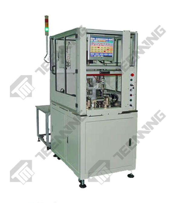 |
Servo-controlled needle winding for stators and BLDC motor cores; two winding positions with a five-axis drive configuration. | Maximum wire diameter: 0.7 mm | Maximum winding speed: 420 RPM; actual speed depends on wire and workpiece geometry. |
TM-M2504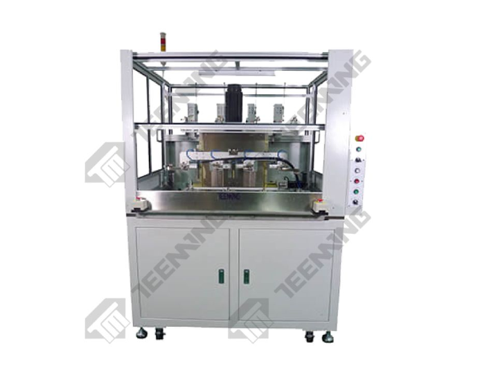 |
Four-position, seven-axis needle winding for stators and BLDC motor cores. | Maximum wire diameter: 0.7 mm | Maximum winding speed: 420 RPM; actual speed depends on wire and workpiece geometry. |
TM-FDW1504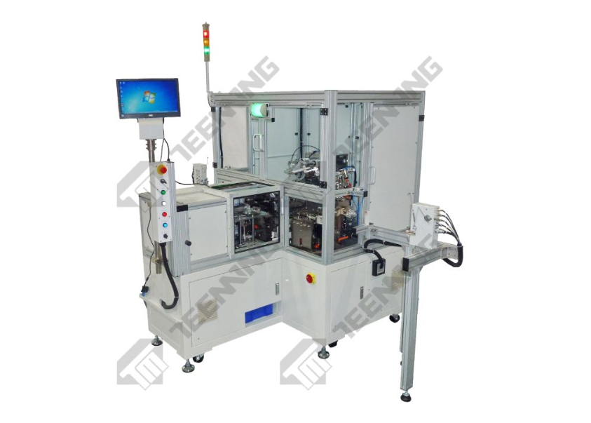 |
High-speed flyer winding for rotors with hook or bar commutators. | 0.12–0.3 mm or 0.3–1.0 mm | Up to 3,000 RPM; product diameter and height: 20–90 mm; 6–36 rotor slots. |
TM-F3502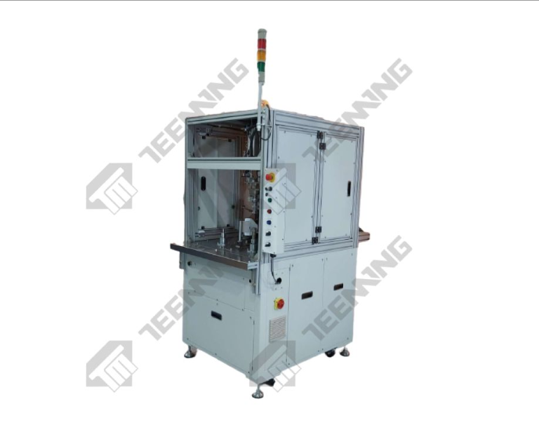 |
Flyer winding for outer-winding motor cores and larger workpieces. | 0.15–1.6 mm | 10–3,000 RPM; product diameter up to 200 mm; thickness 10–50 mm; 4–40 slots. |
Flyer Stator Winding Production Line
Machine specifications may change as equipment is improved. Final machine selection, achievable speed, and winding quality depend on the approved workpiece, wire, tooling, winding pattern, and process requirements.
View the complete automatic motor winding machine range.
Motor Winding Automation and Production-Line Integration
A motor winding machine may operate as a standalone station or as part of a complete production line.
Depending on the application, the winding process can be connected with:
- Robotic or mechanical loading
- Pin insertion
- Wire tension monitoring
- Lead-wire routing
- Wire cutting
- Soldering or welding
- Taping
- Resistance or electrical testing
- Vision inspection
- Product unloading
- Production-data collection
- MES communication
The integration plan should be based on the required cycle time, product variation, inspection method, traceability requirements, and available factory layout.
A programmable tensioner may also be used to control different tension stages during acceleration, winding, deceleration, and lead-wire handling. View Teeming’s tensioners for coil winding.
Motor Winding Machine FAQs
1. What is coil winding?
Coil winding is the manufacturing process of placing insulated conductive wire around a core, bobbin, stator, rotor, or other component. The finished coil generates a magnetic field when current flows through it and is used in motors, transformers, relays, solenoids, inductors, and other electromechanical products.
2. What are electric motor coils?
Electric motor coils are wound conductors that create magnetic fields when energized. Depending on the motor design, the coils may be installed on the stator, rotor, or armature. Their turn count, wire size, direction, insulation, and placement must match the motor’s electrical and mechanical specifications.
3. What does a motor winding machine do?
A motor winding machine controls or automates wire feeding, tension, winding direction, turn count, wire placement, and workpiece indexing. Depending on the configuration, it may also handle pin wrapping, lead routing, cutting, loading, unloading, inspection, and production-line communication.
4. What is the difference between needle and flyer winding?
Needle winding uses a reciprocating or multi-axis needle to guide wire through or around stator slots. Flyer winding uses a rotating flyer arm to guide wire around a stationary or indexed workpiece. The correct method depends on slot access, core geometry, wire diameter, speed, and tooling requirements.
5. How does wire tension affect motor coil quality?
Excessive tension may stretch the conductor, damage insulation, or distort the coil. Insufficient tension may create loose turns, unstable dimensions, and irregular wire placement. The correct tension depends on the wire, insulation, winding speed, guide path, and required coil structure.
6. What information is required to select a motor winding machine?
Prepare the product drawing, sample, wire material and diameter, turn count, winding direction, slot or pole count, lead-wire requirements, target cycle time, production volume, inspection requirements, and desired automation level. These details allow the manufacturer to evaluate the winding method, tooling, tensioner, and machine configuration.
7. Can one motor winding machine produce different products?
A machine may support multiple products when the workpieces fall within its verified wire, travel, speed, and dimensional ranges. Different products may require dedicated fixtures, nozzles, wire guides, tension settings, and program recipes. Engineering evaluation is required before confirming product compatibility.
Conclusion
Coil winding connects electrical design with practical motor manufacturing. Turn count, wire size, tension, direction, insulation, winding pattern, and machine motion must work together to produce an electric motor coil that meets the required specification.
The right motor winding machine is therefore not simply the fastest available model. It is the system that matches the stator or rotor geometry, wire range, production volume, quality controls, changeover requirements, and downstream automation plan.
To evaluate a winding process, provide Teeming Machinery with your product drawing, workpiece sample, winding specification, target cycle time, and required inspection method. Our engineering team can review the application and recommend a suitable machine, tooling, tension-control, and production-line configuration.